FEC200 GONOGO Test
This document describes both the hardware and software considerations for this special purpose test.
The purpose of this test is to allow external special purpose testers (such as Stored Charge for example) to be used in conjunction with the FEC200.
These tests must produce either GO/NOGO or Low/Good/High test results and they must be connected to separate test contacts which are placed one or more index positions before the contacts used by the FEC200.
The FEC200 tester receives the test results and delays them the required number of indexes so that they may be combined with the FEC tests.
The default delay pattern is described here but the defaults can easily be changed if necessary to accommodate larger delays.
The test results for test head #1 are delayed two indexes and the results of test head #2 are delayed only one index. If this seems odd, please think of it this way:
If there are two added test heads, the first one encountered will be special external test #1. The next one will be external #2 followed finally by the FEC200 test head. In this arrangement the #1 test head is two positions ahead of the FEC200.
Since FEC normally does not supply the external tester (although we sometimes do), we normally don't have control of the connections from the external testers to the FEC200. The following example of a Low/Good/High configuration is typical but other arrangements are possible.
There are two TTL level logic inputs for each two external testers on each of the four multiplex stations. Taken as a binary number, the state of these 2 inputs could be 0-3. The inputs are normally pulled high so is unconnected, the input value would be 3.
Assume that a "Low" result pulls the "2" bit low. This would make the input value 1.
A "High" result pulls the "1" bit low making the input value 2. A "Good" result would leave both inputs high for a value of 3.
When logging or "Watching," the value of these inputs is displayed as a "reading."
Many other arrangements could be done but this will illustrate the possibilities.
Before showing a sample test, there is one more important point to make regarding the FEC200 limit comparison method. The FEC limits are "inclusive" that is, if you program >10V <12V, both 10.0V and 12.0V would pass. Of course, 9.9V and 10.1V would fail. It is important to keep this in mind when programming the GONOGO test.
Here is a test using the above assumptions and with the test head two positions back (this would be test head #1):
Another important programming consideration is that, since the FEC200 tester controls the indexing of the handler (with its "End of Test"), the external test MUST have a shorter test time. If necessary add extra time in the FEC200 test program.
HARDWARE INTERFACE
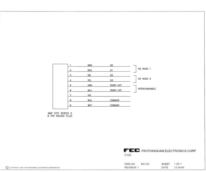
There is a 9-pin round connector on the FEC200 back panel for each of the four multiplex stations. This is NOT intended to connect to the 9-pin connector on our VF40 tester. If connecting to a VF40, the cable would connect to the 37-pin connector on the VF40 end.
Each input connector on the FEC200 can accommodate up to two external testers. For each tester there is a "Common" or Ground connection, a low going "Start Test" output, and 2 TTL level inputs for test results to be input.
See the drawing for the cable C133 in the technical manual for pin connections. "GO NOGO 1" refers to the inputs for a test head two indexes back and "GO NOGO 2" refers to the head that is one index back.
The TTL level inputs can be driven by relays such as those in some Stored Charge and Capacitance testers or by open collector "Bin" drivers such as those in the FEC VF40 testers. Of course, any TTL or other 5V logic drivers would be suitable.
The Start Test output of the FEC200 can not be connected directly to the Start Test input of the VF40. The output of the FEC200 is an open collector driver, which is normally "OFF" "High." The VF40 input requires a nominal +12V to start, although the actual threshold is below +5V. A couple of suitable interface circuits are shown below.
The open collector "Bin" outputs of FEC testers as well as the relay outputs of many Stored Charge or Capacitance testers may be "Wired Ored" that is, connected in parallel to the same input of the FEC200 external interface connector. Therefore if you wish, you could connect all "reject" bin outputs in parallel and connect to the same input of the FEC200. This would pull that input low if any reject bin occurred.