
Frothingham Electronics | For more information, visit us at www.frothingham.com
FEC
Home / PLS500
/ Click to view a .pdf of
PLS500
pages
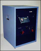
FEC PLS500 Diode Tester
The PLS500 automatic tester is designed primarily to do SURGE testing either as single pulses or with Forward and Reverse bias, according to methods 4066-1 or 4066-2. In addition, it can also test VF with rectangular pulses and THERMAL RESPONSE either in DVF (mV) or degrees per watt. All three test types may be performed in a single test program.When doing 4066-1 or -2 testing, the PLS500 can deliver up to 20 Amps Io and up to 1300V VR. The steady state Io and VRM are delivered for a user programmable number of cycles followed by a single half cycle of SURGE (up to 1000A peak) and a single half cycle of VRSM. The above can then be repeated a programmable number of times.
The THERMAL RESPONSE tests can be done with heating currents up to 20A for long pulses and up to 100A for 10ms. The available IM current for these tests is programmable from 1 to 256mA in 1mA steps. All other relevant parameters for these tests are programmable.
- Thermal Response Testing
- Peak Reverse Bias to 1300V
- Peak Forward Test to 1200 Amps
- Works with Automatic Handlers
- Micro Computer Controlled
- Digital Readout
- Go No-go Outputs
- Energy Storage Bank
- Will Not Cause Line Surges
- Local or Remote Programming
The DC and rectangular pulse currents are accurate to ± 0.5% and 0.05% of full scale. The peak amplitude of half-sine pulses is accurate to ±1% and 0.1% of full scale.
The accuracy of the voltage readout circuits is ±0.25% and 0.02% of full scale.
In its normal stand-alone operation the tester is controlled by a built-in microcontroller. It is programmed by a keypad and LCD display terminal (12 keys,16×2 display).
A software package allows the tester to be controlled by a PC.
Of course the Io for the -2 method is DC. However, the duty cycle is still programmed in equivalent 60HZ power line cycles.
The VF corresponding to the peak surge current during the final pulse is measured and reported. This voltage can also be compared with both maximum and minimum limits. The half sine pulses produced by the tester are 8.3ms in duration, regardless of the local power line frequency. This is done by controlling a constant current source with the output of a Digital-Analog Converter (DAC). The DAC is being driven with data stored in tables in the controller's RAM.
The high voltage supply that delivers the VRM half sines is isolated from the low voltage forward supply by a large SCR that is turned on during the forward half cycle. The reverse supply can deliver roughly 10mA into a shorted load and is designed to tolerate this condition.
The user can easily monitor the 4066 operation with an oscilloscope with one channel watching the reverse voltage on the cathode and a second channel monitoring the forward current using the 200A/V output connector on the front panel (BNC).
VF can be measured with a single rectangular pulse of programmable amplitude and width. The maximum current for short pulses is 1200A.
DVF and THETA are both THERMAL RESPONSE tests, and are performed in substantially the same way. The difference is that DVF reports the change in VF at a low current before and after a heating pulse. THETA makes the same measurement but reports the results in Degrees Celsius per Watt of applied power. In order to do this, the tester must know the change in VF per degree at the low current (IM). The user must program in this value.
The PLS500 can be used as a stand-alone tester, programmed by the built-in keypad and LCD display. However, the tester comes bundled with our program VFS2, which can control the tester from a host PC. This is a much easier way to program the tester. More important than ease of programming is the variety of plots and statistical reports that can be created.
The tester comes with a built-in PC* and with LCD monitor, keyboard and printer.
*The PLS500 is supplied with a PC that runs a version of DOS called FreeDOS, which is distributed free under GPL licensing.
PLS500 Second
Page